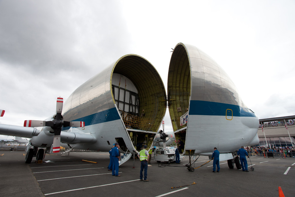
Proof that whales can fly? The super-guppy landed at Redstone airfield today, carrying the cryo composite tank test article. Looking forward to breaking it! :)
Wednesday, March 26, 2014
Friday, March 07, 2014
Cryo Composite Tank Development Testing
NASA’s Game ChangingDevelopment Program is aiming to advance composite materials technology for the purpose of manufacturing light weigh liquid hydrogen (LH2) fuel tanks for the next generation of rockets, possibly starting as an upgrade to the SLS upper stage. Current technology involves baking composites in an autoclave, which is not very feasible for a 5.5 meter (~18’) diameter tank. A second hurdle is the fact that hydrogen has a way of permeating and escaping from most containers. If successful, this program will pave the way for industry to produce high performance composite materials at less cost, without the need for large autoclave ovens.
NASA’s Marshall Space Flight Center (MSFC) supported pressurized LH2 testing of the initial smaller 2.4 meter (~8’) tank last July.
![]() |
| Small tank test, July 2013 |
![]() |
| Artists Rendition of the 5.5 Meter Tank |
![]() |
| Super Guppy- the aircraft that swallows space ships. |
This tank will endure more than mere pressurization with LH2. MSFC’s Special Test Equipment Branch (ET50) is designing a test apparatus to apply a combination of compression, moment, and shear loads. The final test is to failure. The test will take place at the 4699 facility, visible on Google Maps at https://www.google.com/maps/@34.6284812,-86.6728124,135m/data=!3m1!1e3
The test apparatus is composed of upper and lower “load spiders”. The test article will sit on the pads of the lower spider. The upper spider will be supported over the test article by a large pedestal structure. Sixteen load lines will push and pull between the top of the test article and the bottom of the upper spider. In the FEA contour images below, the hardware is depicted reacting to a complex loading. Deflections are highly exaggerated for clarity- the beams will only move about .13 inches. Two shear towers sit on either side of the setup, with the shear beam spanning them. Two additional load lines attached to the beam impart a shear load into the side of the test article. The upper spider is about 33 feet in diameter, for reference.
![]() |
| Shear Tower |
![]() |
| Lower Spider |
![]() |
| Shear Beam |
Update: The tank is at MSFC http://swampcastle-scrapbook.blogspot.com/2014/03/the-cryo-composite-tank-has-landed.html
Monday, January 14, 2013
Recent Test of the Gas Generator from the Saturn F1 Engine
The joy of smoke and fire, from a test stand I helped analyze. J Below is a photo of a test of the gas generator off of a vintage F1 engine. There's more info and a video on the NASA website.
Below
is a photo of the test stand being modified for the test, followed by a
screenshot of the model. There isn’t much room to move around, with all
of the piping systems twisting around the structure, test article, and
each other.
Here is a section of the LOX system, followed by analysis of the new LOX support structure.
Sunday, November 06, 2011
Last Discovery Mission
This is a picture of Discovery's last crew, STS 133, with everybody's signature. Discovery carried my EVA tools all those years ago, and the final mission is the one that I supported with the test fixture analysis. The fixture was for testing to support the repair of the external tank stringer, which cracked during tanking.
Monday, September 19, 2011
Snoopy
I never thought I'd get a Silver Snoopy! And my good friend got one at the same time, making it that much more special.
TBE Article
Marshall Star Article
NASA Awards Database
TBE Article
Marshall Star Article
NASA Awards Database
Friday, June 10, 2011
Closing the door.
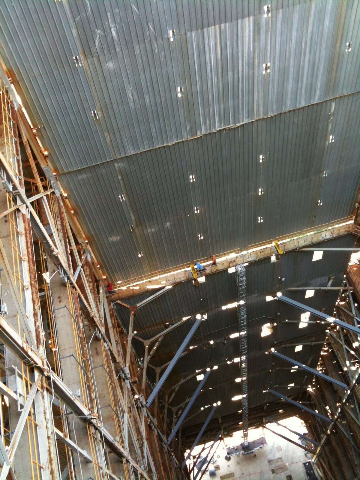
In my earlier post, the shuttle scaffolding was being removed from the Dynamic Test Stand to make room for Ares I.
They have completed the removal process.
Ready to be outfitted for Ares I...
Sadly, they have now closed the door back on an empty test stand. No rocket in the building. I hope we'll have one to test some day soon.
They have completed the removal process.
Looking down from the top floor.
Looking down from mid-building
Looking across from mid-building
Looking up from mid-building.`
Ready to be outfitted for Ares I...
Closing the door, prepping to put the roof back on.
Sadly, they have now closed the door back on an empty test stand. No rocket in the building. I hope we'll have one to test some day soon.
Monday, May 16, 2011
Stringer test fixture
These are photos of the hardware that was the subject of the stress analysis that I posted about, below.
Photos of the stringer test fixture.
Thursday, March 10, 2011
Salute to Discovery
This is my salute to Discovery, with a vintage 1960's Astronaut Snoopy and my mission cup from Discovery's STS-51 in the foreground, and one of the big test stands out my office window in the background. Snoopy is somewhat worse for wear, because he was a gift from my father, and my brother and I enjoyed him as kids.
Wednesday, March 09, 2011
FEA of Stringer Test Fixture
Here are some clips from a stress report I collaborated on. The hardware was designed specifically for the ET-137 Intertank that flew with STS-133. The fixture was used during the effort to repair and qualify the tank for flight, after a fracture was found in the stringer at the rivet line.
Hardware description:
This test fixture is designed to
test a one-stringer section of STS External Tank panel under loading conditions
similar to those experienced during tanking. The simulated loads are
experienced when the bottom of the tank contracts under the cryogenic thermal
load, but the top of the tank is at ambient temperature. This fixture uses
mechanical means to deliver the simulated load without applying any actual
thermal load to the test panel. The loading is intended to cause cracking in
the stringers similar to that of the flight article.
Thursday, November 05, 2009
Common Bulkhead test Rapid Prototype model
Here's a desktop-sized rapid prototype of our test fixture. It is made of plastic, and painted. The actual fixture will be about 20 feet across.
This is the Common Bulkhead sandwiched between my barrels. You can see the barrels in the above assembly, where the Upper Dome covers the Common Bulkhead.
Tuesday, October 27, 2009
Ares 1-X
A nice shot of Ares 1_X on launch morning. This is the one with a live first stage, and dummy upper stage and booster. The fisrt stage is made of five SRB segments, which makes it the longest solid rocket stage used to date. The shuttle SRB's are four segments each.
Monday, March 02, 2009
Common Bulkhead Test poster
Wednesday, February 18, 2009
Ares photos
Here's a link to some good photos, and ARIES I stackup time-lapse for the first-stage test, with dummy upper stage and dummy Orion.
Friday, November 21, 2008
Cool shot of an engine test
They tested the launch abort motor in Utah. I like the four distinct plumes. Here's the article, with some videos too.
Thursday, November 20, 2008
Shell Buckling
This is from my first project at TBE/NASA. I used some of my real-time modeling skills to make the CAD models look more realistic. The test article, lit so brightly that it looks like a warp engine, was a scale version of a rocket skin, and built with greatest care. Then, we squeezed it until it buckled with a wonderful boom, all in the name of science. They got some very good data from it. Here's an article about it. I call it the "Can Crusher".
They have buckled a second and third article, with plans to do more. We may also build another one of these, twice the size, without the brown towers.
My poster, rendered from my Pro/E model.

The actual article, built from my prints, all ready for the first test.
They have buckled a second and third article, with plans to do more. We may also build another one of these, twice the size, without the brown towers.
My poster, rendered from my Pro/E model.

The actual article, built from my prints, all ready for the first test.
| From Swamp Castle |
Tuesday, November 18, 2008
Focus on Marshall video
Cool! My test is in Focus on Marshall, episode 31, November 2008! Mine is the shell buckling, which they talk about in the video, after the ullage motor bit. I guess I didn't rate for the interview, but whatever. Fist test may be tomorrow!
Friday, September 26, 2008
Thursday, September 25, 2008
MSFC Dynamic Test Stand Photos
Here are some photos Bryan took the day we went up on the dynamic test stand, and then spliced together later. In these photos, the floor is still configured for shaking the shuttle "Enterprise". You can see roughly shuttle-shaped holes in the floor, where it was suspended.
They are currently removing the shuttle floors, and will be reconfiguring to hold ARES I. This tower is one of a pair that make a familiar part of the Huntsville skyline. Until recent years, it was the tallest structure in Alabama. The view from the top is awe inspiring.
The crane on top, as seen from the roof:

Looking down from the roof, through the open door.

At the level of the door threshold, looking up at the roof crane.

Looking across the door opening. Looks like the door is 7 floors tall. Here you can see that the bottom of the doorway is still pretty high above the ground.

Looking up, you see the side of the test stand, then the door slid down, then the door opening, and the cranes on top.

A shot from the inside, looking at the layers of walkways.

Looking down through a shuttle-shaped hole.

Imagine slipping a shuttle, nose first, down through this hole.

They are currently removing the shuttle floors, and will be reconfiguring to hold ARES I. This tower is one of a pair that make a familiar part of the Huntsville skyline. Until recent years, it was the tallest structure in Alabama. The view from the top is awe inspiring.
The crane on top, as seen from the roof:

Looking down from the roof, through the open door.

At the level of the door threshold, looking up at the roof crane.

Looking across the door opening. Looks like the door is 7 floors tall. Here you can see that the bottom of the doorway is still pretty high above the ground.

Looking up, you see the side of the test stand, then the door slid down, then the door opening, and the cranes on top.

A shot from the inside, looking at the layers of walkways.

Looking down through a shuttle-shaped hole.

Imagine slipping a shuttle, nose first, down through this hole.

Labels:
ares,
dynamic test stand,
enterprise,
msfc,
nasa,
space shuttle,
space shuttle enterprise
Subscribe to:
Posts (Atom)