NASA’s
Game ChangingDevelopment Program is aiming to advance composite materials technology for the purpose of manufacturing light weigh liquid hydrogen (LH2) fuel tanks for the next generation of rockets, possibly starting as an upgrade to the SLS upper stage. Current technology involves baking composites in an autoclave, which is not very feasible for a 5.5 meter (~18’) diameter tank. A second hurdle is the fact that hydrogen has a way of permeating and escaping from most containers. If successful, this program will pave the way for industry to produce high performance composite materials at less cost, without the need for large autoclave ovens.
NASA’s Marshall Space Flight Center (MSFC) supported pressurized LH2 testing of the initial smaller 2.4 meter (~8’) tank last July.
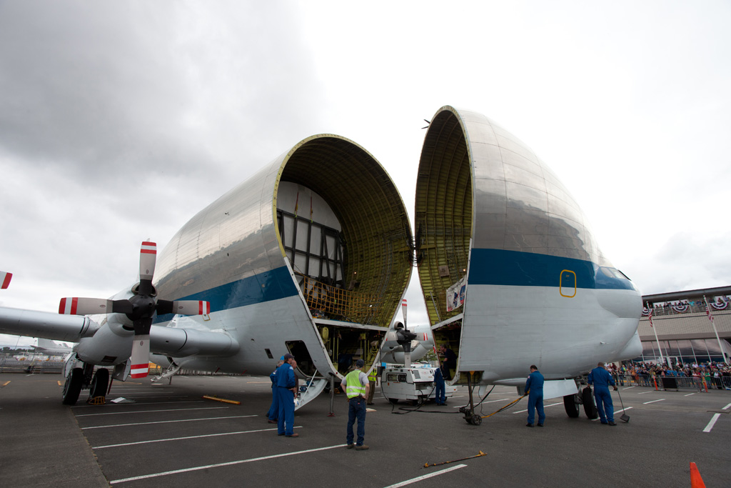
This year, MSFC will test the 5.5 meter (~18’) tank, which will be flown in from Boeing’s Seattle facility on the Super Guppy.
This tank will endure more than mere pressurization with LH2. MSFC’s Special Test Equipment Branch (ET50) is designing a test apparatus to apply a combination of compression, moment, and shear loads. The final test is to failure. The test will take place at the 4699 facility, visible on Google Maps at
https://www.google.com/maps/@34.6284812,-86.6728124,135m/data=!3m1!1e3
 |
| Test stand 4699: Upper load spider is sitting on the ground next to the test stand. The lower spider is barely visible in the center bottom of the test stand, where it is in shadow. The shear towers are at upper right and left corners of the test stand, slightly taller than the rest of the stand. |
My job is to make sure the failure occurs in the test article, and not in the structure applying the enormous test loads. I am a member of ET50’s in-house stress analysis team. I broke down the test apparatus into more manageable parts, and created Finite Element Analysis (FEA) versions of each, using plate models. These analyses give a very accurate picture of how the structure will react under the test conditions, and allow me to advise the design team early on if there are any potential issues that need to be addressed.
The test apparatus is composed of upper and lower “load spiders”. The test article will sit on the pads of the lower spider. The upper spider will be supported over the test article by a large pedestal structure. Sixteen load lines will push and pull between the top of the test article and the bottom of the upper spider. In the FEA contour images below, the hardware is depicted reacting to a complex loading. Deflections are highly exaggerated for clarity- the beams will only move about .13 inches. Two shear towers sit on either side of the setup, with the shear beam spanning them. Two additional load lines attached to the beam impart a shear load into the side of the test article. The upper spider is about 33 feet in diameter, for reference.
 |
| Upper Spider, on top of Pedestals |
 |
| Shear Tower |
 |
| Lower Spider |
 |
| Shear Beam |